Skip to content

Battery Management System

BMS 1500V

High-voltage BESS & industrial storage

A modular battery management system built for industrial BESS, solar-plus-storage, and power conversion applications up to 1500 V DC. Protection logic operates independently of higher-level control; hardware and firmware safety paths run in parallel.

1500 V DC

Max bus voltage

±500 A

Hall sensor range

±2 mV

Cell voltage accuracy

4–18

Cells per CMU

±1 %

HV measurement accuracy

140 mA

Passive balancing current

01

Protection

Safety functions are implemented with hardware and firmware redundancy. Protection paths operate independently of the system controller and trigger under any operating condition, including software faults.

Nokto BMS 1500V board — top view

Overvoltage & Undervoltage

Cell, module, and bus voltage monitored continuously. Protection triggers at configurable thresholds; overvoltage trip at 1500 V DC on the bus.

Over/Undertemperature

Up to 8 NTC sensors per battery module. Thermal runaway protection triggers on upper thermal limit; undertemperature block prevents cold-charge damage.

Overcurrent

Charge and discharge current monitored continuously via two galvanically isolated Hall-effect sensors. A fast-acting fuse on the positive HV rail provides a secondary hardware-level trip.

Isolation Monitoring

The Battery Junction Unit monitors isolation resistance between HV lines and chassis ground. Differential current anomalies between positive and negative rails detected during operation.

Contactor Driving & Monitoring

Dual main contactors with auxiliary contact feedback. State verified on open and close. Welding and failure-to-open faults detected; remaining service life tracked.

Precharge & Emergency Stop

Inrush current controlled via series resistor during startup. The E-STOP input triggers an unconditional opening of all contactors across all networked SMUs, overriding any software state.

02

Monitoring & State Estimation

The BMS reports state continuously to the EMS Gateway and, via Modbus TCP/IP, to any upstream controller. All state estimates are computed on-device; no cloud dependency for safety or operational decisions.

SoC
State of Charge — remaining capacity from voltage and current integration.
SoH
State of Health — long-term capacity and performance degradation across the pack lifetime.
SoE
State of Energy — usable energy in kWh, accounting for voltage and temperature conditions.
SoP
State of Power — maximum safe charge and discharge power at current conditions, without triggering protective shutdowns.
Cell voltage
Individual cell voltages at ±2 mV accuracy, 0–5 V range per cell. Up to 18 cells per CMU.
Temperature
Up to 8 NTC sensors per module; thermal map updated every 100 ms regardless of string depth.
Event log
Operational events, fault conditions, and alarm history written to non-volatile memory for audit and diagnostics.

Architecture note

Cell-level acquisition is distributed across Cell Management Units (CMUs), each dedicated to one battery module. CMUs communicate with the main controller via an isolated TPL daisy-chain running every 100 ms, independent of chain depth.

Galvanic isolation is provided at every node boundary. TPL transformers carry 4300 V DC for 60 seconds and 1600 V DC continuously for 15 years, rated per IEC 61010-1.

High-voltage isolation is independently monitored by the Battery Junction Unit (BJU), which reports isolation resistance without depending on cell measurement paths.

Nokto BMS 1500V CMU (Cell Management Unit) board
03

Specifications

ParameterMinTypMaxUnitConditions
DC Bus Operating Voltage1501500V DCNormal operation
DC Bus Overvoltage Threshold1500V DCProtection trigger
DC Bus Undervoltage Threshold150V DCProtection trigger
Maximum Continuous Current±500ACharge / Discharge
HV Measurement Accuracy±1%Full scale
Current Measurement Accuracy±0.5%Full scale

BJU — Battery Junction Unit

Monitors HV bus voltage and isolation resistance. Reports to the BMU; operates independently of cell measurement paths.

Nokto BMS 1500V BJU (Battery Junction Unit) board
04

Communication Interfaces

External interfaces are designed for integration with inverters, EMS gateways, and SCADA systems. Internal interfaces handle inter-module coordination and are not accessible to external systems.

External

Ethernet — Modbus TCP/IP, SunSpec

100 Base-T Ethernet for configuration, monitoring, and remote diagnostics. Modbus TCP/IP compliant with the SunSpec standard. Primary integration interface for EMS gateways and inverter controllers.

Internal

CAN 2.0B — Inter-SMU bus

ISO 11898-2:2016 CAN bus for parallel string coordination and internal diagnostics. Also used by BMS Control Center software for parameter configuration. Not exposed as an external integration interface.

Internal

TPL Daisy-chain — CMU communication

Isolated high-speed differential daisy-chain between the main controller and CMUs. Galvanic isolation to 4300 V DC at each node boundary. Acquisition cycle 100 ms, independent of chain depth.

I/O

E-STOP, Fan, Status LED

MicroClasp 2-pin header for E-STOP (normally-open, 12 V) and fan control (12 V / 0.1 A). Front-panel RGB LED indicates contactor state, fault conditions, and warning levels during operation.

Nokto BMS 1500V — communication interfaces panel
05

System Configuration

Three deployment configurations cover standalone plants through multi-string portfolios. All configurations share the same hardware platform; topology is set during commissioning.

Configuration A

Stand-Alone

Single SMU operating independently. Suitable for single-string BESS, testing, and development deployments.

SMUs
1
External interface
Ethernet / Modbus TCP/IP
Typical use
Single-string BESS
Configuration B

Network — Main / Secondary

Multiple SMUs on a shared CAN bus. One unit operates as Main; remaining units operate as Secondary, coordinated network-wide. Scales to parallel strings within a single installation.

SMUs
2 or more
Coordination
CAN bus, Main/Secondary
E-STOP scope
Network-wide
Configuration C

EMS-Controlled

BMS connected to an EMS Gateway for remote monitoring, parameter access, and integration with the EMS Cloud platform. Operates autonomously at the edge; cloud connectivity is optional.

EMS interface
EMS Gateway / Modbus
Remote access
EMS Cloud (optional)
Edge autonomy
Full; no cloud dependency
06

Software Tools

Two companion tools are included at no additional cost. Both are provided as portable executables; no installation or licensing server required.

Included

BMS Control Center

Desktop application for commissioning, configuration, and diagnostics. Connects to the BMS over CAN (local) or via EMS Gateway (remote). Supports Windows x86_64 and Linux x86_64.

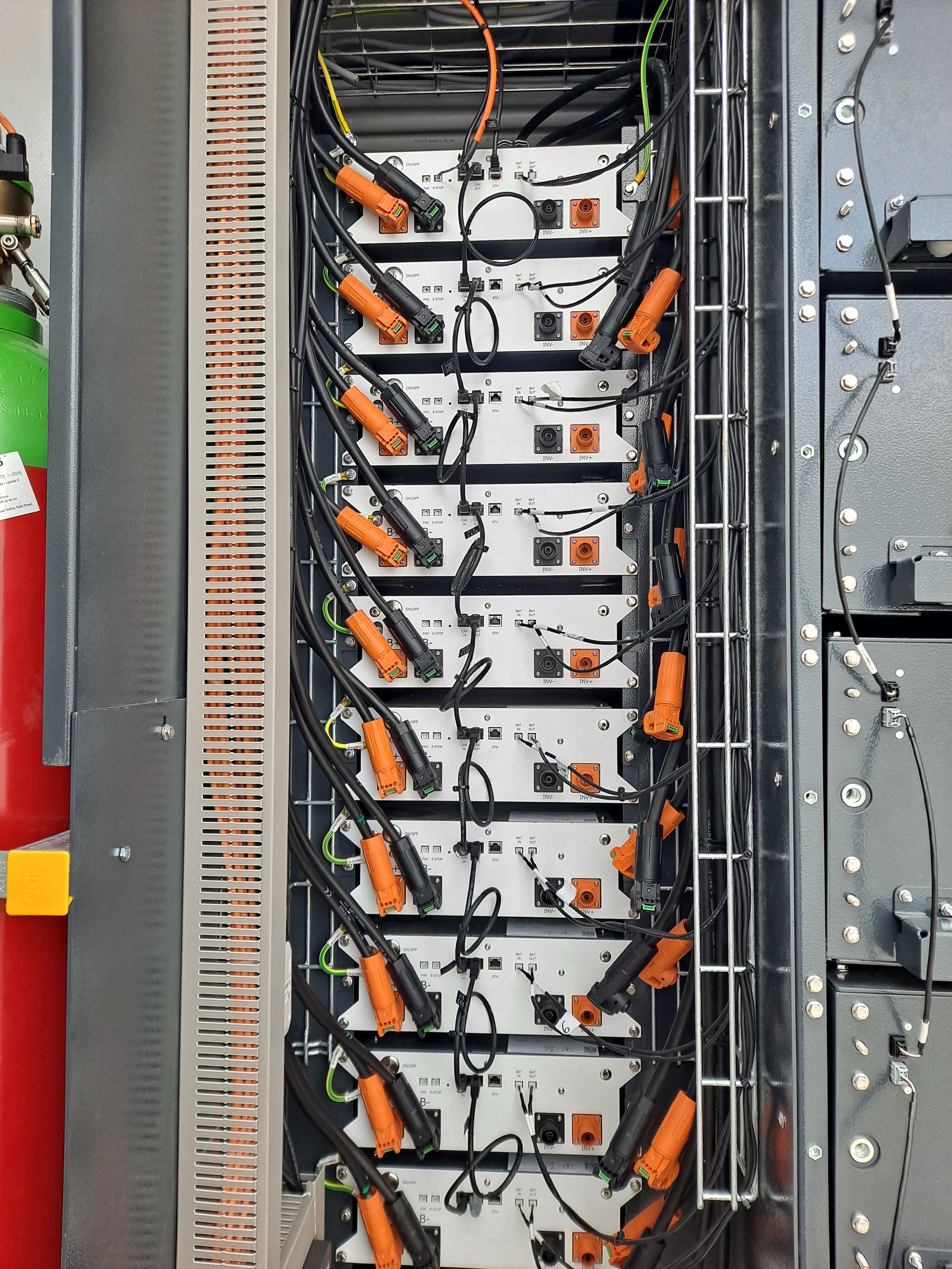
  • SMU and BMU monitoring — live display of SoC, SoH, system voltage, current, power, and contactor state across all connected strings.
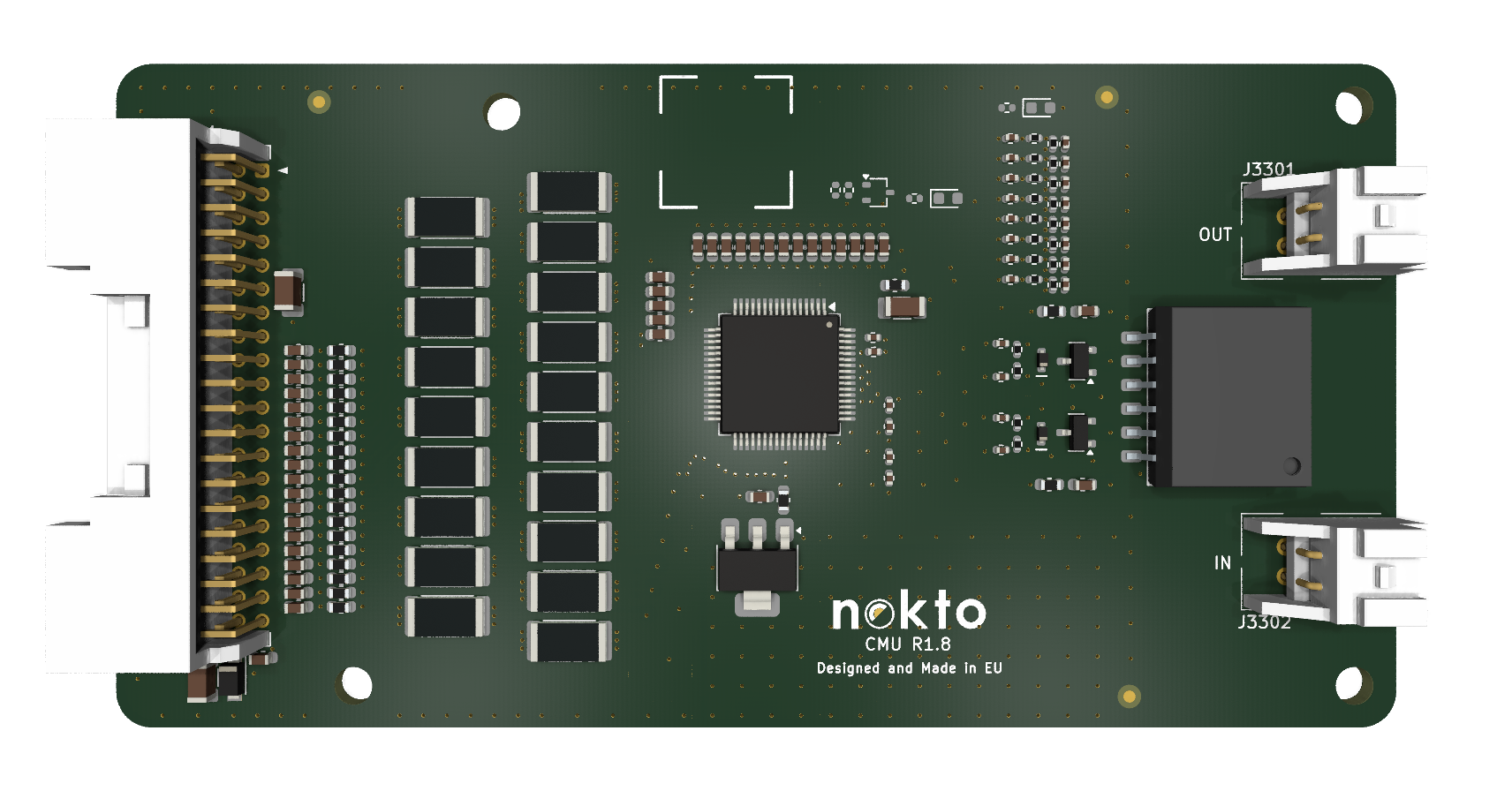
  • Cell-level visibility — per-cell voltage (±2 mV), SoC, SoH, and temperature status for each CMU in the selected string.
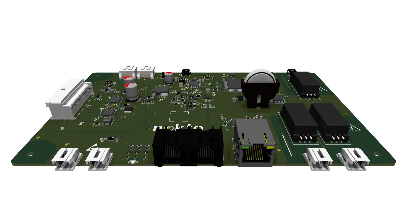
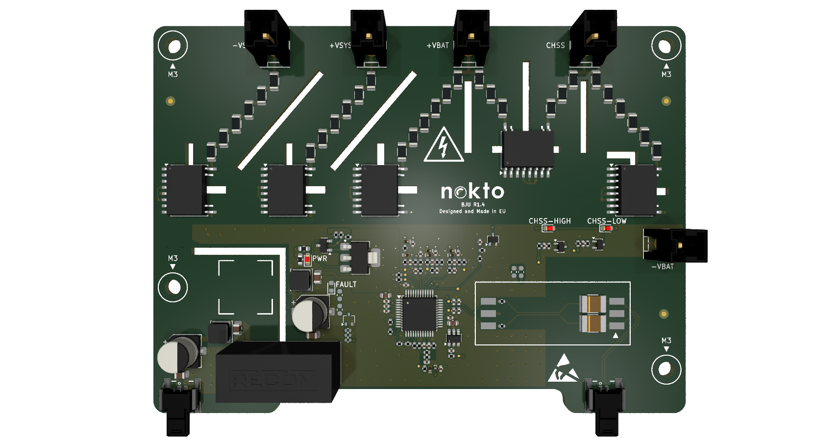
  • BJU monitoring — live HV bus voltage readings (VSYS+, VBAT+, VSYS−) and isolation resistance (ISO Pos, ISO Neg) in MΩ.
  • Error management — 33 error codes with state tracking, occurrence counts, timestamps, context snapshots, and corrective guidance. Color-coded severity: green / yellow / red / blue (unchecked).
  • Parameter configuration — view and write all threshold parameters (cell voltage limits, temperature cutoffs, overcurrent levels, reconnection delays) with import/export via CSV.
  • Firmware update — bootloader and application flashing per BMU, with version readback and progress confirmation via CAN trace.
  • CAN trace — raw frame capture with timestamp, ID, data, cycle time, and direction. Records to .csv and .log for offline analysis.
Platform Windows & Linux x86_64
Interface PCAN, SocketCAN, Remote, File
RAM 4 GB min
Included

BMS Viz Tool

Companion desktop application for visualizing recorded BMS data. Loads CSV files exported from BMS Control Center and renders signal plots and statistical summaries for post-session analysis.

  • Signal plot viewer — load a CSV recording and select individual signals for time-series visualization. Supports multi-signal overlay.
  • Statistics panel — min, max, mean, and range computed per signal across the loaded session.
  • CSV compatibility — reads files recorded directly from the BMS Control Center Trace tab. Each column represents all signals per BMU; timestamp in the first column.
  • Analytics tab — session-level summary view for reviewing system behavior across a full commissioning or test run.

Typical workflow

  1. 01 Record a session in BMS Control Center Trace tab
  2. 02 Export as .csv from BMS-Control-Center/Records
  3. 03 Load file in BMS Viz Tool, select signals to plot
  4. 04 Review statistics and export findings

The Nokto platform

Part of the
Nokto platform.

The BMS 1500V is designed to operate within the full Nokto stack. Pairing with the EMS Gateway and EMS Cloud gives operators visibility and control from cell level to portfolio level through a single interface.